Last Updated on: March/20/2018 |
for 1024x768 & higher screen resolution |
Telephone:+1(774)929-7084 |
| >Downloads>PRG0801 |
Dual Door Bell with LEDs(PRG0801 Application Note Rev. A)By Au Group Electronics Jan. 2008
This document is one of the application notes for Au Group Electronics 8-pin integrated circuit chips: Dual Door Bell with LEDs (Part#: PRG0801P and PRG0801SN). Features
Applications
Absolute Maximum Ratings
Note: Stresses beyond parameters listed here might damage the device. Typical Operation Characteristics
DescriptionThe Au Group Electronics PRG0801 is an 8-pin 8-bit flash microcontroller with integrated program. The PRG0801 is a fun circuit for driving buzzers creating cricket-chirping-like noises and LED blinks at the same time. It has dual input and output interfaces which are independent to each other. It can be used for dual door bell application with LED indications. Also a single door bell circuit can be made if only one door-bell is needed. Its low current consumption feature makes it also a good candidate for battery-powered toys. All the control logics required for circuit operation is contained within the PRG0801 8-pin integrated circuit. Normally only batteries, 2 buzzers, 2 LEDs, 2 switches, and 4 resistors are needed for a completed dual door bell circuit. The PRG0801 use a random algorithm to generate chirps/beeps at random intervals up to 8 to 9 seconds. Between these series of chirps/beeps, the integrated circuit is kept at low power mode in order to conserve batteries energy. Also the push-pull buzzer driver is capable of driving non-self-driver type buzzers without external capacitor. It can work with both self-drive type buzzer and non-self-drive type buzzer. Pin Descriptions: The PRG0801 is available in either 8-lead PDIP package (300 mil), or 8-lead SOIC surface mount package (3.90mm). Au Group Electronics part numbers for both packages are listed here:
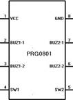
Table 1 Pin Descriptions of PRG0801
Each of the buzzer driver (1 and 2) consists of two output pins (BUZ1-1, BUZ1-2; BUZ2-1, BUZ2-2), the polarity of these two pins is not important. The buzzers and LEDs should be installed in any direction. A resistor should be installed between these two pins to limit the current. Example:Figure 2 illustrates a typical connection of a dual door bell with LEDs system. Battery group B3 could be consisted of 2 to 3 pieces of AA type batteries connected in serial. Resistance of R1 and R3 should typically be 100-150 ohm, and resistance of R2 and R4 should typical be 47K Ohm. D1 and D2 are LEDs with typical forward voltage of 1.8 to 2.5V. BUZ-1 and BUZ-2 should be 1.5-5V non-self-drive or self-drive type buzzers. S1 and S2 are push buttons.
Figure 2 Typical circuit connection of a dual door bell with LEDs system At power on,
After that, the PRG0801 will enter low power mode if no S1 or S2 events. At low power mode, the S1 and S2 switch can wake up the PRG0801 and trigger separate events on BUZ1/D1 and BUZ2/D2. If S1 button is pressed at low power mode,
A single push on S1 will keep “buzzer driver 1” circuit on for 8-9 seconds. Then the PRG0801 will be back to low power mode. If S2 button is pressed at low power mode,
A single push on S2 will keep “buzzer driver 2” circuit on for 8-9 seconds. Then the PRG0801 will be back to low power mode. If S1 and S2 were pressed consecutively at low power mode, Both BUZ1 and BUZ2 will be on for a maximum period of 8-9 seconds. ============================ End ============================
|