Last Updated on: March/20/2018 |
for 1024x768 & higher screen resolution |
Telephone:+1(774)929-7084 |
| >Downloads>PICkit 2 Programmer-To-Go Application Note |
Application Note for BB0703 (PICKit 2) "Programmer-To-Go" Function(Program without a PC !!!)By Au Group Electronics April 2008
When a PIC program (hex file) is loaded into the EEPROM of Au Group Electronics BB0703 (PICkit 2), it can be used as a standalone programmer to program PIC chips, no PC is needed!!! There are many different ways to use the BB0703 (PICkit 2) "Programmer-To-Go" function. This document will show you one step by step. What you need:Software:
Hardware:
Step by step guide on BB0703 (PICkit 2) Programmer-To-Go
Figure 1 – Connect BB0703 (PICkit 2) to PC
"PICkit 2 Programmer" window pops up, 2 possible situations may be displayed depending on the previous setting of PICkit 2 V2.50.
Figure 3 – Situation 1 - Message “No Device Found” displayed
Figure 4 – Check “Manual Device Select” Situation 2 - Message "-Select Part-" displayed, as shown in figure 5, continue with step 4.
Figure 5 – Situation 2 – Message “-Select Part-” displayed
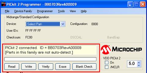
Figure 6 – Check communication PICkit 2 Programmer displayed the message “PICkit 2 connected. ID = BB0703RevA00009 [Parts in this family are not auto-detect]”, as shown in figure 7.
Figure 10 – Import hex file
Figure 11 - Select hex file Message "Hex file successfully imported" displayed, as shown in figure 12.
Figure 12 – “Hex file successfully imported”
Figure 13 – PICkit 2 Programmer-To-Go
Figure 14 – Programmer-To-Go wizard
Figure 17 – Download complete
Figure 18 – Connection of BB0703 (PICkit 2) to target chip The ICSP signal of each color wire on RJ12 programming extension cable is identified in table 1. Table 1 - Signal definition on RJ12 programming extension cable
Note: Table 1 can only be referred with a connection complied with Figure 18. The connection of using Au Group Electronics BB0703 (PICkit 2) to program target board/chip without a PC is demonstrated in figure 19.
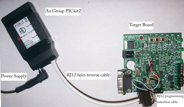
Figure 19 – Connect BB0703 (PICkit 2) with target board and power supply All the parts demonstrated in figure 19 are available from Au Group Electronics website: www.AuElectronics.com
During programming, Power and Busy LED remain lit, Target LED may be ON or OFF accordingly, figure 20 illustrated a BB0703 (PICkit 2) Programmer-To-Go with Target LED lit, which indicates a +5V voltage was supplied to target board through the programming cables.
Figure 20 - BB0703 (PICkit2) programmer-to-go
Note: PICkit 2 is a trademark of Microchip inc. |