Question 8 - How to Program PICs (DIP) with Breadboard?
(AU Groups BB0703 (PICkit2) Application Note)
By Au Groups
Jan. 2008
There are many different approaches to program the DIP (Dual In-Line) PIC chips without very expensive programming fixtures.
This document provides one of the many possible solutions for Microchip PIC fans and Engineering students. It illustrates step by step instructions on how to use the AU Group Electronics BB0703 (PICkit2) and breadboard for downloading programs into the DIP PIC chips.
What you need:
-
Au Group Electronics BB0703 (Enhanced PICkit 2 System, AU Group Electronics part #: BB0703 )
-
RJ12 programming extension cable (Au Group Electronics part #: CBL-RJ12-Program)
-
RJ12 6 pin Reverse cable (Au Group Electronics part #: CBL-RJ12-RVS)
-
Target Chips in DIP package, for instance: PIC12F508-I/P, PIC18F4550-I/P
-
Breadboard
-
USB cable
-
Application software installed on PC: MPLAB IDE or PICkit 2 programmer
How to connect the target PIC chip to PC for programming:
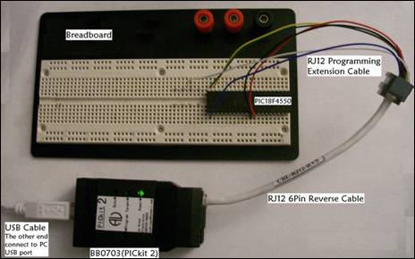
As illustrated in figure 1, by using USB cable, RJ12 6-pin reverse cable, and RJ12 programming extension cable, the target chip can be connected to your PC through BB0703 (PICkit 2),.
Figure 1 Programming connection
Note: Make sure using the exact parts as described in figure 1. Otherwise, ICSP (In-Circuit Serial Programming) signal sequence on programming cable might be different than table 1 illustrated.
As shown in Figure 1, the signal of each color wire of RJ12 programming extension cable is listed in table 1:
Table 1 signal definition on RJ12 programming extension cable
Color of the 6 wires on RJ12 Programming Extension cable |
Signal |
Blue |
VPP |
Black |
VDD-Target (+5V) |
Red |
VSS (GND) |
Green |
ICSPDAT (PGD) |
Yellow |
ICSPCLK (PGC) |
White |
AUX-OUTPUT (Not used in ICSP) |
Pin Number/Signal Identification of Target PIC Chips:
The following figures show two examples of ICSP pins on two DIP microcontrollers: a PIC12F508-I/P and a PIC18F4550-I/P. For any other type of chips, please refer to related Microchip Data Sheet.
PIC12F508-I/P
For PIC12F508-I/P, pin 1, 4, 6, 7, and 8 will be used for ICSP programming, these pins are highlighted with the same wire color of RJ12 programming extension cable, as shown in figure 2.
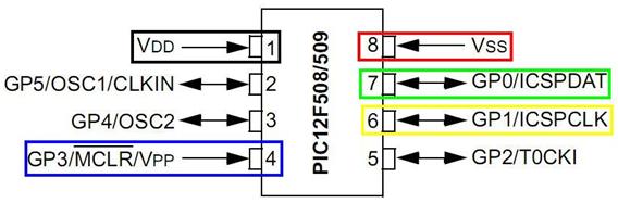
Figure 2 PIC12F508 Pins/Signals Identification
PIC18F4550-I/P
Pin 1, 11, 12, 39, and 40 of PIC18F4550-I/P are used for ICSP programming, and they are illustrated in figure 3 with the same wire color as the RJ12 programming extension cable.

Figure 3 PIC18F4550 Pins/Signals Identification
Step by Step connections:
-
Insert a target DIP PIC chip to breadboard.
-
Inset the 5 wires of RJ12 programming extension cable to respective position of the breadboard where the above 5 ICSP-programming-pins seated.
-
Using USB cable to connect BB0703 (PICkit 2) with PC.
-
Using RJ12 6 pin Reverse cable (Au Group Electronics part # CBL-RJ12-RVS) to connect RJ12 programming extension cable and BB0703 (PICkit 2).
-
Program the target chip with PC application software: MPLAB IDE or PICkit 2 programmer. (step by step operation is illustrated in next chapter.)
-
After target chip is programmed, disconnect “RJ12 programming extension cable” and BB0703 (PICkit 2) by removing one end of the “RJ12 6Pin reverse cable” on either side first, then, take the programmed-chip off the breadboard.
-
If more chips need be programmed, repeat above step from 4 to 6 after new chip is inserted into the breadboard.
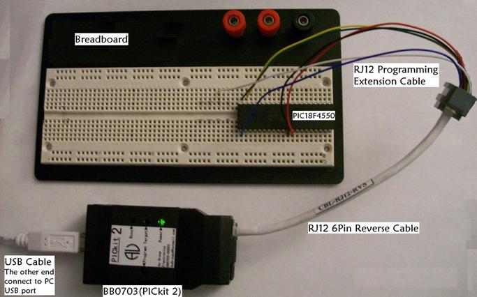
Figure 4 Demo connections with breadboard (using PIC18F4550)
Programming with PICkit 2 Programmer or MPLAB IDE
After the target chip is connected as figure 4 shows, you may program the chip through one of the following application software: by using PICkit 2 Programmer or by using MPLAB IDE.
Using PICkit 2 Programmer
-
Double click shortcut “PICkit 2 programmer” on desktop, as shown in figure 5.

Figure 5 PICkit 2 programmer shortcut
-
“PICkit 2 Programmer” window shows up, select PIC12F508 from the device drop down list, as shown in figure 6.
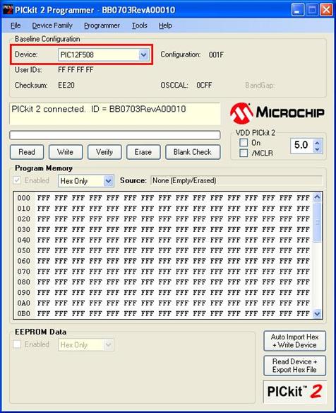
Figure 6 PICkit 2 Programmer window
-
Click “File/Import Hex” to load hex file, as shown in figure 7.
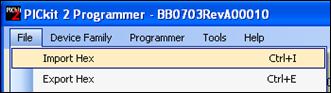
Figure 7 Import Hex file
-
Click “Write” button, the selected hex file will be programmed into the target chip, and “Programming Successful” message will display, as shown in figure 8.
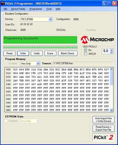
Figure 8 Programming Successfully
-
If more chips will be programmed, repeat 1-4 after a new blank-chip is installed as shown in figure 4. If same hex is used, you don’t need re-load the hex file.
Using MPLAB IDE software
-
Double click shortcut “MPLAB IDE” on desktop, as shown in figure 9.

Figure 9 MPLAB IDE shortcut
-
Click “Configure/Select Device…”, “Select Device” window opens up, select “PIC18F4550” from the device drop down list, then click “OK”, as shown in figure 10. PIC18F4550 will show up in the bottom status bar (not shown here in any pictures).
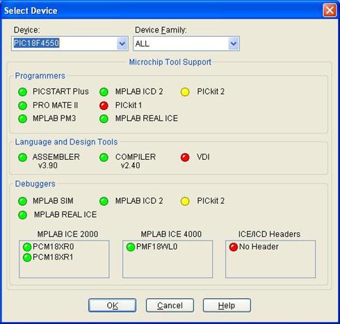
Figure 10 Select Device
-
Click “File/Import…” to open a xxx.hex file, the output window will show a hex file loaded, as shown in figure 11
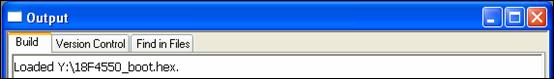
Figure 11 Load hex file
-
Check the configuration Bits from: Configure/Configuration Bits…. Make changes if necessary.
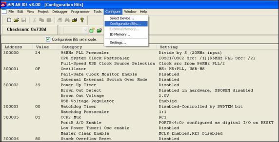
Figure 12 Verify Configuration Bit
-
Click “Programmer/Select Programmer/PICkit 2”, as shown in figure 13.
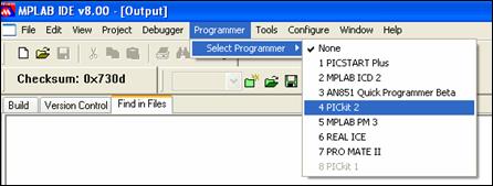
Figure 13 Select Program Device
-
PICkit 2 will initialize and a message “PICkit 2 Ready” will show up, as shown in figure 14.
Note: the message in the green frame may not display, it depends if there is a newer version of PICkit 2 operating system or not. Whenever there is a newer version available, it will be downloaded automatically by default. (The red highlighted icon is the programming icon.)
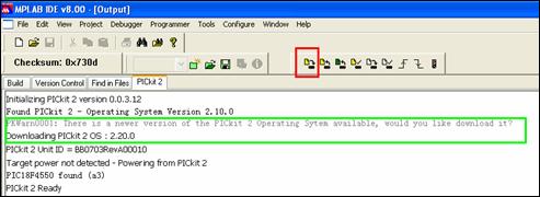
Figure 14 PICkit 2 is connected and ready
-
Click program icon, the hex file will be burned into the target chip. And similar message as shown in the blue frame will be displayed (see figure 15).
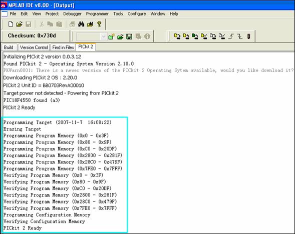
Figure 15
Note: After the chip is programmed, please disconnect the "RJ12 programming extension cable" and the "BB0703 (PICkit2)" by removing one end of the “RJ12 6Pin reverse cable” first, then, take the programmed chip off the breadboard.
-
If there are more chips to be programmed, please repeat steps 1-7 after the chip is inserted into the breadboard. Also you don’t need re-load the hex file if the same hex is used.
================================== End =================================