Au Group Electronics logo
Last Updated on: March/20/2018
for 1024x768 & higher screen resolution
Telephone:+1(774)929-7084

Order Au J1939 simulator


>Downloads>SAE J1939 Simulator Gen II

User Manual  for Au SAE J1939 Simulator-Gen II Ver 1.00A (simplified edition)

By Au Group Electronics
July 2008

Note: Due to the webspace limitation, a full edition of this document is only available upon request.

Au SAE-J1939 Simulators Ver 1.00A are well designed devices capable of simulating majority of SAE-J1939 signal on a vehicle network. A typical SAE J1939-15 network topology is illustrated in Figure 1.


Figure 1 – Typical SAE J1939-15 network topology for Au SAE-J1939 Simulator(s)

6 editions of SAE-J1939 simulator Ver 1.00A are provided by Au Group Electronics to meet various users' needs:

  • SIMJ1939-001: Au SAE-J1939 Simulator Ver 1.00A - Engine Basic Edition
  • SIMJ1939-002: Au SAE-J1939 Simulator Ver 1.00A - Engine Basic Plus Edition
  • SIMJ1939-003: Au SAE-J1939 Simulator Ver 1.00A - Engine Premium Edition
  • SIMJ1939-004: Au SAE-J1939 Simulator Ver 1.00A - Engine Premium Plus Edition
  • SIMJ1939-005: Au SAE-J1939 Simulator Ver 1.00A - Vehicle Platinum Edition
  • SIMJ1939-006: Au SAE-J1939 Simulator Ver 1.00A - Vehicle Platinum Plus Edition

PLUS Edition = Non-Plus Edition + PC Remote Terminal Program

The "Plus" editions have all the functions of "non-Plus" editions, plus a PC Remote Terminal program which can be used to control and display SAE J1939 data on PC screen. A license management toolset provides the capability of upgrading the Simulator from basic edition to premium/platinum edition. “Non-Plus” edition is able to be upgraded to “Plus” editions.
Minor and Major Software code (firmware) upgrade can be in-field updated by Au PIC Bootloader.
Annually support and minor upgrade service is available at Au Group Electronics (Order #: SVS-SIM-J1939).
Major upgrade to Ver 2.00A is available at Au Group Electronics (Order #: FIRJ1939-001).

Engine Basic Edition(s):

  • "Statically" or "dynamically" generate most of the basic engine data
  • Two push buttons (UP and DOWN) are used in "static mode" to adjust data outputs
  • In "dynamic mode", data cycles automatically in its range
  • LEDs indicate the control step value and push button operations
  • Buzzer sound also reflects push button inputs, and can be enabled /disabled

Engine Premium Edition(s):

  • Includes all Engine Basic Edition functions
  • Includes Premium features on SAE-J1939 Transport Protocols:
    • Engine DM1/DM2 warnings (support both single packet and multi-packets)
    • Engine “Red Stop” and “Amber” lamp warnings
    • Water in fuel indicator
    • Engine DM3

Vehicle Platinum Edition(s):

  • Includes all Engine Premium Edition functions
  • Includes Vehicle Network features (3 controller applications have been implemented):
    • ABS related signals
    • Transmission related signals
    • Engine Configurations

This document will introduce major hardware features, important parameters, operating instruction, and data configuration for all 6 editions of Au SAE-J1939 Simulators.

MAJOR FEATURES:

An Au SAE J1939 Simulator is showing in figure 2a


Figure 2a – Au SAE J1939 Simulator (Gen II)

The major features for Au SAE-J1939 Simulator (Gen II) are listed below:

  • Compact size: 4-1/8" L X 1-3/4"W X 7/8"H
  • Enclosure color: Black or PC white
  • Smart features: Recall last operating mode at power-on, capable of generating dynamic data, etc.
  • Ease of use: Au SAE J1939 Simulator is also designed with production line operator and sales person in mind. No software setup experience or CAN protocol configuration skill required. After a network is physically connected, simply power up the simulator, it will dynamically generate J1939 data when in dynamic mode.
  • SAE J1939-15 type II ECU:It contains an internal 120Ω load resistor for easy network setup.
  • 9 LED indicators: POWER, RANGE, WARNING, UP+100%, DOWN+0%, 80%, 60%, 40%, 20%
  • 1 buzzer
  • 3 push buttons: (MENU, DOWN, UP) The SAE-J1939 signal can be adjusted by push buttons
  • 1 RS232 interface: for software update, license management and remote control (Plus editions only)
  • Power supply: +10V~+32V DC, Nominal voltage: +12V DC or +24V DC; 250 mA max.
  • Operating temperature:  -4 ˚F to 185 ˚F (-20 ˚C to 85 ˚C)
  • Static MODE and Dynamic MODE
    • Static mode output static J1939 signal, which still can be changed manually
    • Dynamic mode automatically change the output value of SAE-J1939 signal
    • Two modes can be switched easily
  • 1 DB9 male connector for Power, Ground, CAN_H and CAN_L
  • Accessory cables are available and must be ordered separately, both RS232 Serial Extension Cable (part #: CBL-RS232-01) and 4-wire CAN Cable for DB9 Male Connector (part #: CBL-CAN-01, which provides power supply and CAN network connection to the simulator) are available and can be ordered separately
  • Protections on J1939 CANH, CANL interface: Build with Common-Mode Choke and TVS (Transient Voltage Suppressor) protection
  • In-field license upgrade: Simulator license can be in-filed upgraded to higher editions, e.g. an Engine Basic Edition can be upgrade to an Engine Premium Edition.
  • In-field software code update capability: Software code can be in-field updated with Au PIC Bootloader, for instance, annual update code or custom-made codes can be re-programmed to gain new or special features.
  • Annual support and minor upgrade services are available (Order #: SVS-SIM-J1939)
  • Major firmware upgrade service (Order #: FIRJ1939-001, upgrade from Ver. 1.00A to Ver. 2.00A) is available
  • Custom design available

SUPPORTED SAE J1939 PARAMETERS

Engine Basic Edition(s):

Au SAE J1939 Simulator Engine Basic Edition(s) support majority of SAE J1939 engine parameters:

  • Engine Speed (RPM)
  • Wheel Based Vehicle Speed (MPH)
  • Engine Oil Pressure
  • Engine Coolant Temperature
  • Battery Potential (Voltage) Switched
  • SAE J1939 Fuel Level
  • Engine Turbocharger Boost Pressure
  • Engine Instant Fuel Economy
  • Engine Fuel Rate
  • Accelerator Pedal Position
  • Engine Intake Manifold 1 Temperature
  • Engine % Load at Current Speed
  • Engine Trip Distance
  • Total Vehicle Distance
  • Engine Total Hours of Operation
  • Response  for Engine Hour Request
  • Engine Clock (HH:MM)
  • Response for Engine Clock Request
  • Engine Clock setup
  • Cruise Light
  • SAE J1939 Acknowledge protocol
  • Engine Address Claiming
  • Engine Address CANNOT Claim
  • Response for Address Claim Request
  • Address Conflict Response with Contention
  • Engine DM1 Red Stop Lamp OFF status
  • Engine DM1 Amber Lamp OFF status
  • Engine DM1 (Health-heart-beat)*
  • Water-in-Fuel Indicator (Health-heart-beat)*

* Health-heart-beat: normal signal only, no warning, signal repeats in SAE defined “heart-beat” rate.

Engine Premium Edition(s):

Au SAE J1939 Simulator Engine Premium Edition(s) support all SAE J1939 parameters listed with Engine Basic Edition(s), and the following new features and SAE J1939 parameters:

  • Engine DM1 Warning On/Off control
  • Engine Red Stop Lamp On/Off
  • Engine Amber Lamp On/Off
  • Water in fuel indicator On/Off
  • Engine DM1 Single-Packet warning
  • Engine DM1 Multi-Packet warnings
  • Engine DM2 Single-Packet warning
  • Engine DM2 Multi-Packet warnings
  • Response for DM2 global request
  • Response for DM2 specific request
  • Engine DM3 and Engine DM2 On/Reset control
  • SAE J1939 TP.CM.BAM, TP.DT protocol
  • SAE J1939 TP.CM.EndOfMsgAck, TP.CM.RTS, TP.CM.CTS,  TP.Conn.Abort, TP.DT protocol

Vehicle Platinum Edition(s):

Au SAE J1939 Simulator vehicle Platinum Edition(s) support all SAE J1939 parameters listed with Engine Premium Edition(s), and the following new features and SAE J1939 parameters:

  • Engine Configuration
  • ABS address claim
  • ABS Address CANNOT Claim
  • ABS Response Request for Address Claim
  • ABS Address Conflict Response with Contention
  • ABS Red Stop Lamp On/Off
  • ABS Amber Lamp On/Off
  • ABS DM1 (No warning or 1 warning)
  • ABS Heart-beat PGN-EBC1
  • Transmission address claim
  • Transmission Address CANNOT Claim
  • Transmission Response Request for Address Claim
  • Transmission Address Conflict Response with Contention
  • Transmission Red Stop Lamp On/Off
  • Transmission Amber Lamp On/Off
  • Transmission DM1 (No warning or 1 warning)
  • Transmission Oil Temperature
  • Transmission Heart-beat PGN-ETC1

OPERATING INSTRUCTIONS:

All 6 editions of Au SAE J1939 Simulators can be operated by just controlling 3 push buttons. It generates SAE J1939 signal for product developers, testers, operators and manufacturers.

POWER ON:

  • Connect +10 ~ +32V DC to the "+12V power" and "ground" pin on the DB9 male connector, connect CAN_H and CAN_L to the CAN network (figure 2b)
  • The POWER LED lights up.
  • The simulator resumes the last saved operating mode (static mode or dynamic mode).

DB 9 BUS Male Connector
Figure 2b DB9 BUS Male Connector

OPERATING MODE (STATIC/DYNAMIC):

After power on, and connect CAN_H, CAN_L to a J1939 network (figure 2b), the Au SAE J1939 Simulator will work on either static mode or dynamic mode.

  • Static mode: generate steady SAE J1939 signal, two push buttons (UP and DOWN) is used to change the data outputs
  • Dynamic mode: All data automatically change in SAE J1939 defined range without human interfering
  • Press and hold both MENU+UP button for more than 1 seconds to switch between dynamic mode and static mode

PUSH BUTTON FUNCTIONS AND LED STATUS:

Au SAE-J1939 Simulator equipped with 3 push buttons (MENU, DOWN, UP) and 9 LEDs. The position of push buttons, LEDs, BUS interface, RS232 interface, is illustrated in figure 3. Each LED is named after its function.

Position of push buttons, LEDs, bus and RS232 connector
Figure 3 – Position of push buttons, LEDs, RS232 interface, and BUS interface

  • Press MENU button:

Note: The MENU button function is available only on Engine Premium Edition(s) and Vehicle Platinum Edition(s). This button is not used in Engine Basic Edition(s).

    • MENU button is used to control Warning LED on/off. A single press on MENU button will turn on the Warning LED if the Warning LED is off, and vice versa.
    • The "warning LED" will be constant off in Engine Basic Edition(s).
    • If buzzer enabled, a short beep will be heard to reflect a press on MENU button.

In static mode, all* simulated SAE-J1939 signal will be controlled by the control step value, which in turn can be controlled by the UP and DOWN buttons. In dynamic mode, the simulator automatically adjust the control step value by itself, this will generate dynamic J1939 signals.

  • Press DOWN button:
    • DOWN button is used to decrease the values of all J1939 signal*. Press DOWN button once, all simulated data will decrease one step than the previous data until they reached the minimum values.  "DOWN+0%" LED will be triggered on/off.
    • If DOWN+0% LED is on, press DOWN button one time, DOWN+0% LED will be off.
    • If DOWN+0% LED is off, press DOWN button one time, DOWN+0% LED will be on.
    • 80% LED blinks when control step value equal to 80%,
    • 60% LED blinks when control step value equal to 60%,
    • 40% LED blinks when control step value equal to 40%,
    • 20% LED blinks when control step value equal to 20%,
    • DOWN + 0% LED blinks when control step equal to 0%,
    • If buzzer is enabled, a short beep will be heard to reflect a press on DOWN button.
  • Press UP button:
    • UP button is used to increase the values of all J1939 signal*. Press UP button once, all simulated data will increase one step to next data level until they reached the maximum values, "UP+100%" LED will be triggered on or off.
    • If UP+100% LED is on, press UP button one time, UP+100% LED will be off.
    • If UP+100% LED is off, press UP button one time, UP+100% LED will be on.
    • 20% LED blinks when control step value equal to 20%,
    • 40% LED blinks when control step value equal to 40%,
    • 60% LED blinks when control step value equal to 60%,
    • 80% LED blinks when control step value equal to 80%,
    • UP+100% LED blinks when control step value equal to highest value, 100%.
    • If buzzer enabled, a short beep will be heard to reflect a press on UP button.

Note: * The Engine Clock is not controlled by the control step value and push buttons; it runs all by itself just like a real clock.

  • Press and hold both DOWN + UP button for more than 1 second:
    • DOWN + UP buttons are used to turn buzzer on/off.
    • If buzzer is on, press and hold DOWN + UP for more than 1 second will silent buzzer.
    • If buzzer is mute, press and hold DOWN + UP for more than 1 second will turn it on.
    • Both UP+100% LED and DOWN+0% LED will flip their on/off status as a visual indication of this dual-button input.
    • If buzzer enabled, a long beep will be heard to reflect the input of DOWN + UP button.
  • Press and hold both MENU + DOWN button for more than 1 second:
    • MENU + DOWN buttons are used to turn Engine DM2 warning on/off.
    • Both UP+100% LED and DOWN+0% LED will flip their status as a visual indication of this dual-button input.
    • If buzzer is enabled, a long beep will be heard to reflect the input of MENU + DOWN button. Otherwise, no sound will be heard.
    • The Engine DM2 warning messages (on premium and platinum editions) are always on after power-on, it can be reset when an Engine DM3 PGN is received.
    • For repeating-test purpose, after an Engine DM3 PGN is received, the user can either re-power-on the simulator or press and hold both MENU + DOWN button for more than 1 second to turn the Engine DM2 warning on again.
  • Press and hold both MENU + UP button for more than 1 second:
    • MENU + UP buttons are used to switch between static mode and dynamic mode.
    • Both UP+100% LED and DOWN+0% LED will flip their status as a visual indication of this dual-button input.
    • If buzzer enabled, a long beep will be heard to reflect the input of MENU + UP button.

The push button functions are summarized in table 1.

Table 1 Summary of Push button functions

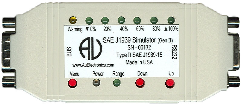
Push Button Operation

Function

Press DOWN button

Decrease all simulated data until it reaches the lowest value

Press UP button

Increase all simulated data until it reaches the highest value

Press MENU button

DM1 Warning On/Off control (N.A. for Engine Basic Edition(s))

Press and hold MENU button when power on

Simulator will enter Bootloader mode, if no communication is detected from a PC Bootloader program within 10 seconds, it will resume normal mode

Press and hold both DOWN + UP button

Buzzer ON/OFF control

Press and hold both MENU + UP button

Switch between Static/dynamic mode

Press and hold both MENU + DOWN button

Engine DM2 ON/Reset control (N.A. in Engine Basic Edition)

AU J1939 SIMULATOR REMOTE TERMINAL

All Au J1939 Simulator editions can be easily integrated into a SAE-J1939 network (with a 4-wire cable). And all PLUS editions can be connected to a PC (with a RS232extension cable), as shown in figure 4.

Typical PC and network connection for J1939 simulator
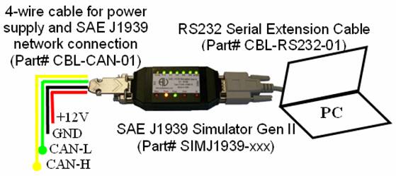
Figure 4 – Typical PC and network Connection of Au SAE-J1939 Simulator

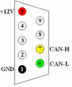
The 4-wire cable (which has a DB9 connector on one end, a pigtail on the other end, can be ordered seperately with Au Part # CBL-CAN-01) for power supply and SAE-J1939 network connection is color coded as shown in table 2.

Table 2 - Color code of 4-wire cable

Color
Signal

Red:

+12 V power supply

White:

CAN-H

Green:

CAN-L

Black:

Ground

Au J1939 Simulator Remote Terminal is available for all Au J1939 Simulator PLUS editions. It is designed for displaying detail information on all simulated SAE-J1939 signal. The interface includes a control panel and a display panel. The control panel is located in the up-left corner. all the other area display info like engine/ABS/Transmission info, warning lamp, etc. as shown in figure 5 - 1, 5 - 2, 5 - 3.

Figure 5 -1 shows the J1939 Simulator Remote Terminal GUI (Graphic User Interface) for vehicle platinum plus edition. All features are active.


Figure 5 - 1 - Au J1939 Simulator Remote Terminal GUI – Vehicle Platinum Plus

Figure 5 -2 shows the J1939 Simulator Remote Terminal GUI for Engine Premium Plus edition. Engine info and warning lamps, engine basic parameters, engine DM1, and engine DM2 are available. ABS info, Transmission info and engine configuration are not available.


Figure 5 - 2 - Au J1939 Simulator Remote Terminal GUI – Engine Premium Plus

Figure 5 -3 shows the J1939 Simulator Remote Terminal GUI for Engine Basic Plus edition. Engine info and Cruise lamps, engine basic parameters are active for this edition.
ABS info, Transmission info, engine DM1, engine DM2, and engine configuration are not available.


Figure 5 - 3 - Au J1939 Simulator Remote Terminal GUI – Engine Basic Plus

  • Display Panel – Engine Basic Parameters

Display the following 16 engine basic parameters: Engine Speed(RPM), Engine hour (Hr), Vehicle speed (MPH), Engine oil pressure (PSI), Engine coolant temperature (F), Battery voltage (V), Fuel level (%), Engine boost pressure (PSI), instant fuel economy (MPG), instant fuel rate (GPH), accelerator position (%), inlet air temperature (F), engine load percentage (%), engine trip (mile), total vehicle distance (mile), and engine clock (HH:MM) (figure 6).
Note: Engine Clock is not controlled by the control step value, it runs by itself like a real clock, and can be setup by PGN 54528.


Figure 6- Display panel – Engine basic parameters

  • Display Panel – Engine DM1

Engine DM1 message could be one packet (without warning or with 1 warning) or multi-packet.
If engine DM1is a single packet, SPN, FMI, OC, CM will display (figure 7-1). If engine DM1 is a multi-packet, "see @ Multi-Packets" will display, “Multi-packets” button will be active (figure 7 – 2), click on it, the whole list of engine DM1 will display. If Engine DM1 or DM2 warning is off, a SAE defined non-warning message will be shown as (0,0,0,0).  

     
Figure 7 -1- Engine DM1 Single Packet                   Figure 7 - 2 - Engine DM1 Multi-Packet

  • Display Panel – Engine DM2

Engine DM2 message could be one packet or multi-packet. If engine DM2 is a single packet, SPN, FMI, OC, CM will display (figure 8-1). If engine DM2 is a multi-packet, "see @ Multi-Packets" will display, “Multi-packets” button will be active (figure 8–2), click on it, the whole list of engine DM2 will display.

    
Figure 8 -1- Engine DM2 Single Packet                   Figure 8 - 2 - Engine DM2 Multi-Packet

  • Display Panel – Engine Configuration

Engine Configuration PGN includes 34 bytes of messages which require transport protocol for multi-packet communication. “Engine Configuration” button will be active on the GUI (Figure 9 -1) for vehicle platinum edition(s).


Figure 9 -1 - Display panel – Engine Configuration

  • Display Panel – ABS DM1

ABS DM1 is a single-packet PGN. If ABS warning is off, a SAE defined non-warning message will be shown as (0,0,0,0); If ABS warning is on, a Brake Switch signal low warning will be shown (597,1,7,0) (figure 10).


Figure 10- Display panel – ABS DM1

  • Display Panel – Transmission DM1

Transmission DM1 is a single-packet PGN. If transmission warning is off, a SAE defined non-warning message will be shown as (0, 0, 0, 0); if the warning is on, a transmission oil warning will be shown as (177, 0, 126, 0) (figure 11).


Figure 11- Display panel – Transmission DM1

As defined by SAE-J1939/21, the Au SAE-J1939 simulator response to different “engine DM2 request” with different transport protocols (illustrated in Table 3).

Table 3 – Transport Protocol for DM2 global/specific request

Request

Transport Protocol

Global request

TP.CM.BAM

TP.DT

Specific request

TP.CM.RTS

TP.CM.CTS

TP.DT

TP.CM.EndOfMsgACK

TP.CM.Abort