Last Updated on: March/20/2018 |
for 1024x768 & higher screen resolution |
Telephone:+1(774)929-7084 |
| >Downloads>Au SAE J1939 Message Center System User Manual |
Au SAE-J1939 Message Center System User Manual
All Copyrights are reserved by Au Group Electronics 2008 Table of Content
Major Hardware and Software Features
Hardware, network topology and Hardware ConnectionAu J1939 message center system includes both hardware and software to receive messages from J1939 network and display those messages with a user-friendly graphic display on PC. HardwareThe hardware is listed below (figure 1):
Au J1939 message center box (figure 1b) is a handheld device with one push button, 2 LEDs (Power, Comm), and 2 DB-9 connectors (a DB-9 female RS-232C connector on RS232 side for PC connection, a DB-9 male connector on Bus side for J1939 network and power supply),
CAN Network topologyTwo possible CAN network topologies of Au J1939 Message Center System (MCS) are illustrated in figure 2.
Hardware Connection at Au J1939 MCB
Connect with PCOne end of the RS232C extension cable (Part# CBL-RS232-01) connects to PC, the other end connects to Au J1939 MCB RS232 side. Connect with SAE-J1939 NetworkThe Au J1939 MCB Bus side is connected to J1939 network by a CAN cable (part# CBL-CAN-01), as shown in figure 3.
Table 1 – color coding of CBL-CAN-01 cable
PC Software (Au J1939 MCS GUI)Parameters displayed on Au J1939 MSC GUIThe PC software for Au J1939 message center system (Au J1939 MCS GUI) provides user friendly graphic interface, which simulates an instrument panel with 6 analog outputs, 17 digital outputs, and 8 message/warning lamps.
The Au J1939 MCS GUI is showing in figure 5.
Following paragraphs will illustrate how to install Au J1939 MCS GUI step by step, also frequent asked questions for Au J1939 MCS are attached. J1939 MCS GUI Installation
Frequent Asked QuestionsHow to Use the Software?The software will function accordingly with J1939 input, no special tune-up required. How to change the serial port?At the top-right side, click "Change" button to bring up "Change Serial Port" window, select desired COM from the drop down list, click “OK” to confirm change (figure 15).
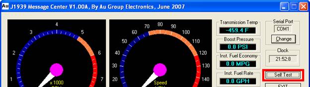
How to enter/exit self test mode?Self Test button on the top right is an On-Off switch, click "Self Test" once will start a self test mode, click "Self Test" again will exit self test mode (Figure 16).
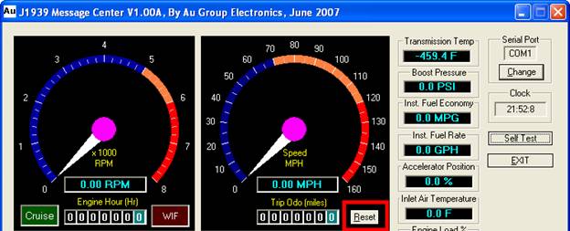
How to reset Trip-odometer?Click the "Reset" button at Trip Odo meter will reset trip odometer to 0 (figure 17), also it will be reset to 0 every time when the program starts. This is only a "Trip" odometer.
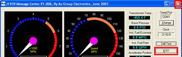
How to exit program?There are 2 ways to exit the program
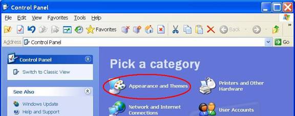
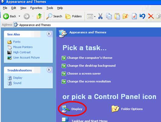
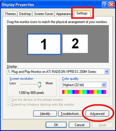
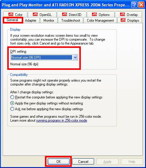
My GUI is only showing partially, is there something wrong?Follow step I to III to change the monitor display setting on PC will solve this issue.
Limited Life Time WarrantyAu Group Electronics provides limited life time warranty to this product under normal use in accordance with the specification and warning, for as long as you own this product. This warranty extends only to the original purchaser of the product, and is not transferable. To exercise your rights under this warranty, you must provide proof of purchase in the form of an original sales receipt/shipping memo that shows the product name and the date of purchase. Any non-authorized modification to hardware will violate this warranty. Shipping cost for any return material will be carried by purchaser. |
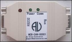
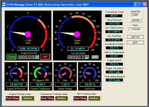
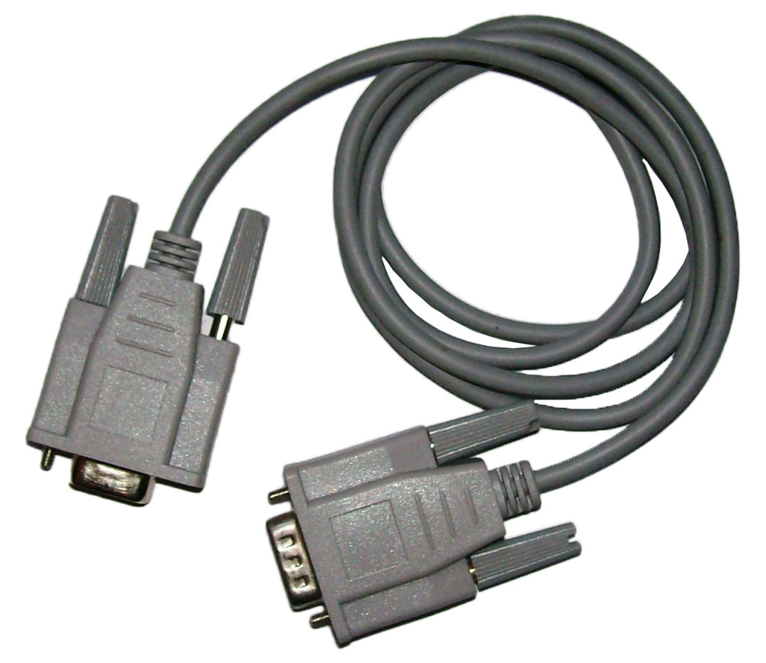

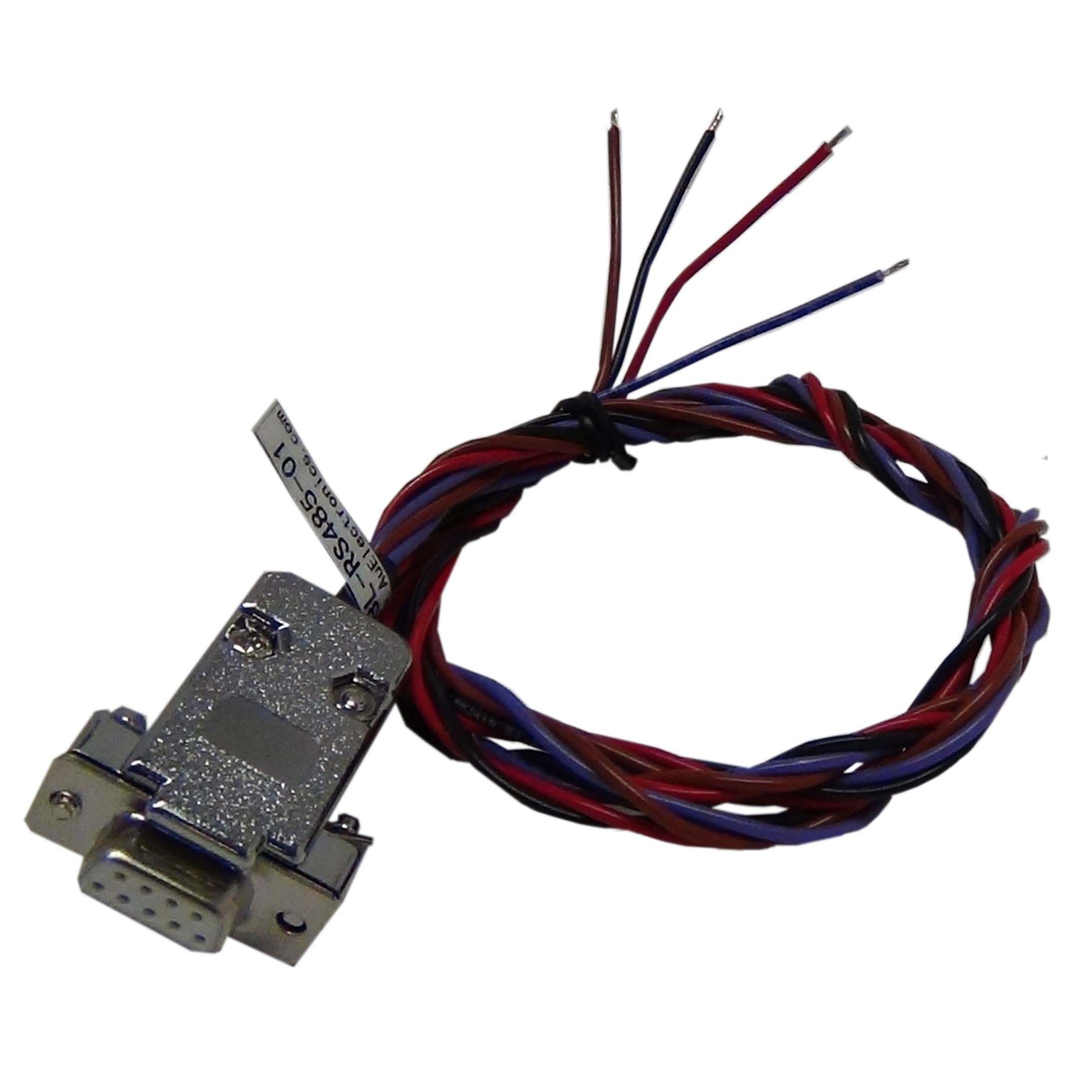
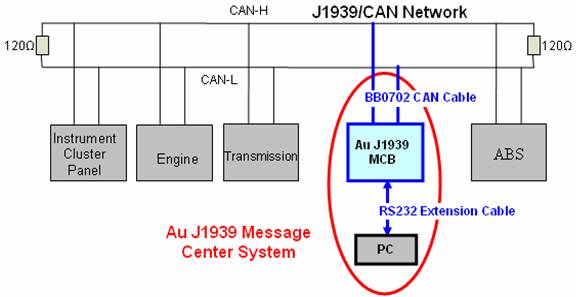
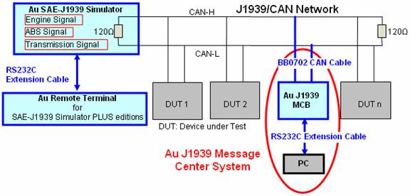
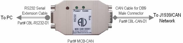
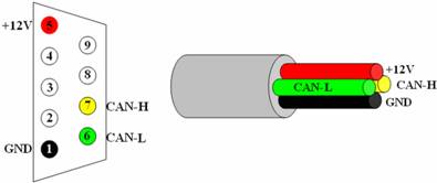
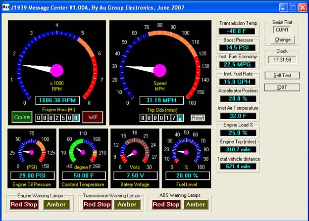 Figure 5 – Au J1939 Message Center System GUI
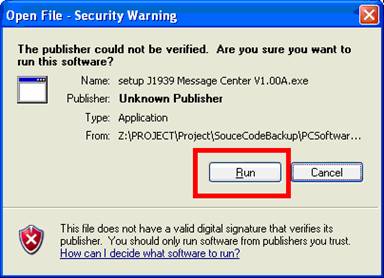
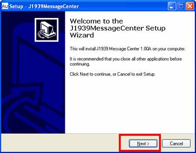
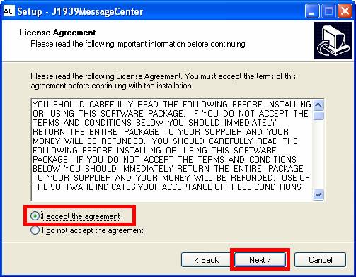
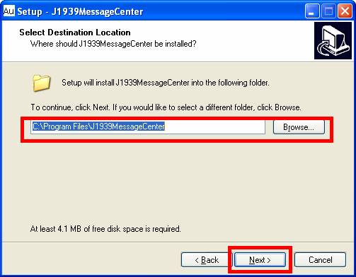

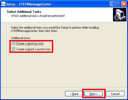
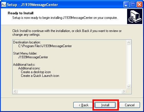
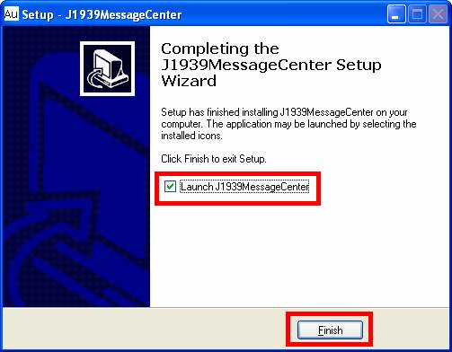
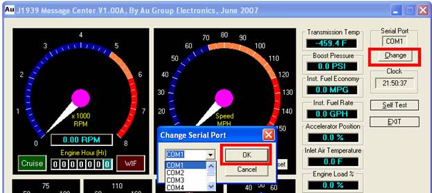 Figure 15