User Manual for 2-in-1 and 3-in-1 Mini-Labs
(Rev. A November-03-2008)
3-in-1 mini-Lab
The 3-in-1 Mini-Lab is a handy, low cost tool capable of programming, debugging and testing Flash-based PIC Microcontroller, KEELOQ HCS, MCP250xx and EEPROMs. It is able to connect SMD or through hole chips with multiple programmers (e.g. Au Group Electronics BB0703, BB0703+, microchip PICkit2, ICD2, ICD3, RealICE, etc.) via a "6-pin ICSP header" or a "RJ12 6P6C socket". Both SOIC-SMD packaging (up to 28 pin) and through-hole packaging (DIP 8, 14, 18, 20, 28, 40) integrated circuits are supported. It also provides unique lab-test circuits, such as: on-board voltage regulators (5V, 3.3V, and 2.5V), pull-up circuit, pull-down circuit, cap connection, bidirectional voltage-level translator, and LEDs, etc.
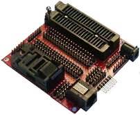
Figure 1
2-in-1 mini-Lab
To meet various customer requirements, for those customers who only need the capability of handling through-hole components, a 2-in-1 mini-Lab is also developed with all the same features as stated in this document, with only the exception of the 28-pin SOIC ZIF (Zero-Insertion-Force) socket not provided on board.
Major Features
-
Dimension: 3.93"L x 3.13"W x 1"H (100mm x 80 x 25 mm)
-
Power supply connector: Ø2.1mm, 9V input, positive center
-
Three On-board voltage supplies: 5V, 3.3V, 2.5V, 100 mA Max.
-
Dual bidirectional I2C/SMBus voltage-level translator
-
RJ12 6P6C socket: compatible with BB0703/BB0703+(s), ICD2/ICD3/RealICE etc.
-
6-pin ICSP header: compatible with Microchip PICkit 2
-
mini-Lab circuits: 6-LEDs, 3 pull-up, 2 pull-down, 1 capacitor for debugging/testing
-
Power LED will illuminate whenever programming activity occurs on the board
-
Jump wire technology guarantee no worry about pin compatibility for future PIC chips
-
12 pieces jumper wires included and extra jumper wires can be ordered separately.
-
SOIC ZIF socket: compatible with any Gull Wing JEDEC device sizes in 0.300" body widths up to 28-pin
-
DIP ZIF socket - compatible with any 8, 14, 18, 20, 28, and 40-pin PIC microcontrollers or other type of semiconductor chips in DIP packaging (0.300-0.600" body widths)
Major Components
The 3-in-1 mini-Lab composed of all components for DIP chip programming, SMD chip programming, and mini-Lab test circuits (such as: power jacket, 5V/3.3V/2.5V circuits, I2C voltage-level translator, ICSP header, RJ12 6P6C socket, connectors to 28-pin /40-pin sockets, 6 LEDs, pull-up/down circuits, etc). The major components and connectors are illustrated in figure 2.
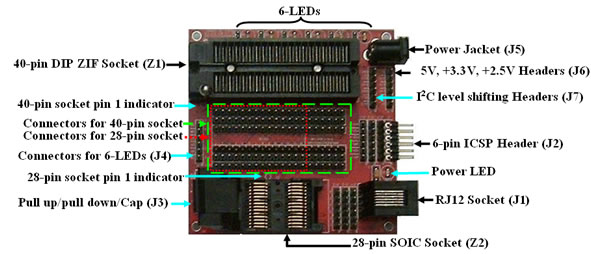
Figure 2
Power Supply: (J5)
A positive center  power jacket J5 (compatible with wall mount power supply PWR-912V-CP) is used for external power supply (+9 volt, 100 mA), the external power supply is regulated to +5V, +3.3V, and +2.5V (J6). power jacket J5 (compatible with wall mount power supply PWR-912V-CP) is used for external power supply (+9 volt, 100 mA), the external power supply is regulated to +5V, +3.3V, and +2.5V (J6).
RJ12 6P6C socket (J1) and 6-pin ICSP header (J2)
-
2 types of ICSP connectors are included: "RJ12 6P6C socket" (J1) and "6-pin ICSP header" (J2), they can be easily connected with most common programmer, e.g. BB0703, BB0703+ (s), PICKit2, ICD2, ICD3, RealICE, etc.
-
A "RJ12 6-pin reverse cable" ( CBL-RJ12-RVS) is required for BB0703 and BB0703+(s).
-
A "RJ12 6-pin standard cable" ( CBL-RJ12-STD) is required for Microchip ICD2, ICD3, and RealICE
-
The 6-pin ICSP header can connect directly with microchip PICkit 2
-
J1 and J2 are connected together and each has 3 rows of 6-pin header (J1-1, J1-2, J1-3, J2, J2-1, J2-2, J2-3) for connection with jumper wires
40-pin DIP ZIF socket (Z1) and / or 28-pin SOIC socket (Z2)
The 40-pin DIP ZIF socket (Z1) and 28-pin SOIC socket (Z2) shared same six rows of 20-pin headers (from JZ-1 to JZ-6). The pin numbering of JZ1 to JZ6 is illustrated in figure 3.
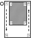
Figure 3
-
DIP Zero-Insertion-Force (ZIF) socket supports DIP packaging up to 40 pins
-
DIP ZIF: Accepts 0.300" to 0.600" center DIP devices
-
DIP ZIF: Accepts leads: 0.015 – 0.045 wide, 0.110-0.280 long
-
DIP ZIF: Standard handle, down is on
-
DIP ZIF: Pin 1 is identified at the position close to handle
-
SOIC Zero-Insertion-Force (ZIF) socket supports SOIC packaging up to 28 pins
-
SOIC ZIF: supports Gull Wing JEDEC device sizes in 0.300" (7.62mm) body widths
-
SOIC ZIF: Tweezers slot for easy manual/auto chip loading/unloading
-
SOIC ZIF: Lid can be actuated from top or side
-
SOIC ZIF: Pin 1 is identified at the top-left corner (Figure 2)
���
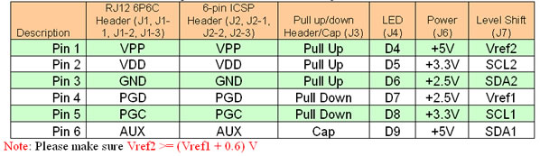
�� Other Header Definitions
The function name of each header pin is defined in the following table:
��
|